
Series Clippers : part 2
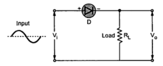 |
| Fig. 1 Negative series clipper |
Note : A series negative clipper is basically a half wave rectifier circuit.
operation :
Consider a circuit shown in the Fig. 1. where diode is connected in
series with the load. Let us analyze this circuit. For a positive half
cycle, the diode D is forward biased. Hence the voltage waveform across RL looks like a positive half cycle of the input voltage.
While for a negative half cycle, diode D is reverse biased and hence
will not conduct at all. Hence there will not be any voltage available
across resistance RL. Hence the negative half cycle of input
voltage gets clipped off. The input waveform and the corresponding
output voltage waveform is shown in the Fig. 2.
Note : For an ideal diode, the output voltage will reach to the same maximum level as that of input, during positive half cycle.
As it clips off negative half cycle of the input it is called series negative clipper.
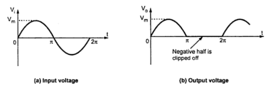 |
| Fig. 2 |
Note : It is not necessary that in such circuits the input voltage waveform has to be a sinusoidal one.
Operation with non-sinusoidal inputs :
The input to the circuit can be of any type as square, triangular etc.
The circuit clips off the negative portion of the input waveform. This
is shown in Fig. 3(a) and (b).
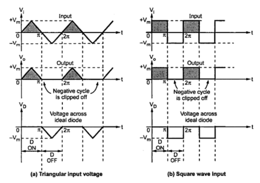 |
| Fig. 3 Waveforms of series negative clipper |
When diode is reverse biased, the negative peak of input appears across
the diode. The diode must be selected so as to withstand this reverse
voltage. Its peak inverse voltage (PIV) rating must be higher than the
reverse voltage appearing across it.
Transfer characteristics :
The working of the circuit can be easily understood if a graph of output against input is available.
Note : The graph of output variable against input variable of the circuit is called transfer characteristics of the circuit.
Thus for the negative series clipper, the graph of against is its
transfer characteristics. The mathematical equation for such a graph,
assuming ideal diode is given by,

The graph showing above mathematical relationship is shown in the Fig. 4.
 |
| Fig. 4 Transfer characteristics with ideal diode |
Effect of cut-in voltage of diode :
It is shown that diode does not conduct till the forward voltage becomes greater than cut-in voltage Vγ of the diode. Hence in series negative clipper, the diode D conducts when Vi > Vγ, where Vγ is generally 0.7 V for silicon diodes. While for Vi ≤ Vγ, the diode D is OFF and Vo = 0 V.
Thus due to cut-in voltage of diodes,
1. Only negative half cycle does not get clipped off but part of positive half cycle till Vi becomes more than Vγ of diode also gets clipped off.
2. The maximum output voltage Vo available is less than maximum input voltage Vm by the amount equal to Vγ.
The mathematical equation for transfer characteristics now becomes,

The effect of cut-in voltage i.e. barrier potential is shown in the Fig. 5(a) and 5(b).
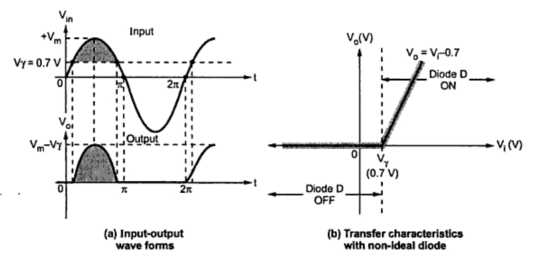 |
| Fig. 5 Effect of Vγ on negative clipper circuit |
Note
: The region for which diode is ON is called transmitting region while
the region for which diode is OFF is called clipping or limiting
region.
Sponsored links :