
power transformer is a static device that, by electromagnetic induction, transmits electrical power from one alternating voltage level to another without changing the frequency. It has two or more windings of wire wrapped around a ferromagnetic core. These windings are not electrically connected, but they are magnetically coupled, i.e., the only connection between the windings is the magnetic flux present within the core.
One of the transformer windings, the primary winding, is connected to an alternating current (ac) electric power source. The second transformer winding, the secondary winding, supplies electric power to loads. If the transformer has three windings, then the third winding, the tertiary winding, also supplies electric power to loads.
The electrical energy received by the primary winding is first converted into magnetic energy that is reconverted back into a useful electrical energy in the secondary winding (and tertiary winding, if it exists).
A transformer is called a step-up transformer if its secondary winding voltage is higher than its primary winding voltage. In a step-up transformer, the primary winding is also called the low voltage winding and the secondary winding is also called the high voltage winding. On the other hand, if the transformer secondary
winding voltage is lower than its primary winding voltage, the transformer is called a step-down transformer. In a step-down transformer, the primary winding is also called the high voltage winding and the secondary winding is also called the low voltage winding.
winding voltage is lower than its primary winding voltage, the transformer is called a step-down transformer. In a step-down transformer, the primary winding is also called the high voltage winding and the secondary winding is also called the low voltage winding.
The transformer is an electrical machine that allows the transmission and distribution of electrical energy simply and inexpensively, since its efficiency is from 95% to 99%, i.e., the transformer operates more efficiently than most electrical devices (Kennedy 1998). This means that the transformer changes one ac voltage level to another while keeping the input power, i.e., the power at the first voltage level, practically equal to the output power, i.e., the power supplied to the loads. In a step-up transformer the secondary voltage is higher than the primary voltage, which means that the secondary current has to be lower than the primary current to keep the input power equal to the output power. Since the power losses in the transmission lines are proportional to the square of the current in the transmission lines, raising the transmission voltage and reducing the resulting transmission currents by a factor of 10 with step-up transformers reduces transmission line losses by a factor of 100 (Chapman 2005). That is why step-up transformers are used in power generating stations so that more power can be transmitted efficiently long distances. Step-down transformers are used in power distribution networks, factories, commercial buildings, and residences to reduce the voltage to a level at which the equipment and appliances can operate. Transformers play also a key role in the interconnection of power systems at different voltage levels. Without the transformer, it would simply not be possible to use electric power in many of the ways it is used today. Consequently, transformers occupy prominent positions in the electric power system, being the vital links between power generating stations and points of electric power utilization.
2. Magnetic Circuits
2.1General
A simple magnetic circuit is shown in Fig. 1. The core is composed of ferromagnetic material with permeability μo (H/m) that is much greater than the permeability μ (H/m) of the surrounding air. The core has a uniform cross-section area Ac (m2). The core is excited by a winding of N turns carrying current i (A). This winding produces a magnetic field in the core. The source of this magnetic field is the ampere-turn ( A.t ) product N.i, which is called magnetomotive force ƒ (A.t) :
ƒ = N.i ................. (1.1)
 |
| Fig. 1 Magnetic circuit |
Ampere’s law states that the line integral of the magnetic field intensity H around a closed path is equal to the net current enclosed by that path (the magnetomotive force for the magnetic circuit of Fig. 1):
 .................. (1.2)
 Assuming that for the magnetic circuit of Fig. 1.1 the magnetic flux density B is uniform across the core cross-section area, the line integral of H is equal to the scalar product Hc.Lc where Hc is the magnitude of H along the mean flux path whose length is Lc (m) :

.................. (1.3)
If we substitute (1.1) and (1.3) into (1.2), we obtain: :
Hc.Lc= N.i = ƒ . .....................(1.4)
For the ferromagnetic material of the core, the following relationship holds between the magnetic flux density B and the magnetic field intensity H :
B = μ.H, ..................(1.5)
where μ (H/m) is the permeability of the ferromagnetic material of the core. The permeability μ can be expressed in terms of the relative permeability μr of the ferromagnetic material and the permeability μo of free space as follows :
μ = μo.μr ..................(1.6)
The permeability of free space is μo = 4. π 10-7(H/m) It should be noted that the relative permeability μo varies with magnetic flux density. The magnetic flux φ (Wb) crossing an area is the surface integral of the magnetic flux density B :

.............(1.7)
According to field theory for the continuity of flux, all the flux that enters the surface enclosing a volume must leave that volume over some other portion of that surface because magnetic flux lines form closed loops. If the magnetic flux outside the core of Fig. 1.1 is neglected, then (1.7) reduces to the following scalar form:
φc = Bc.Ac ................(1.8)
where φc (Wb) is the magnetic flux in the core, Bc (Wb/m2 or T) is the magnetic flux density in the core, and Ac (m2)is the cross-section area of the core. Supposing that the permeability μ of the ferromagnetic material is constant, and since the magnetic flux density is uniform, from (1.5) the following expression is obtained for the calculation of Bc for the magnetic circuit of Fig. 1.1:
Bc = μ.Hc ..............(1.9)
Solving (1.9) for Hc gives:

..............(1.10)
Solving (1.8) for Bc gives:

................... (1.11)
If we substitute (1.10) and (1.11) into (1.4), we obtain:


............ (1.12)
The reluctance Rc of the magnetic core is defined from the following formula:

............(1.13)
The reluctance Rc is expressed in ampere-turns per weber (A.t/Wb Substituting (1.13) into (1.12), we obtain:
ƒ =φc.Rc ............(1.14)
2.2 Analysis of Magnetic Circuits
There is an analogy in the analysis of magnetic circuits with the analysis of electric circuits. This approximation derives from the mathematical similarity of electric and magnetic laws.

In electric circuits, Kirchhoff’s current law states that the algebraic sum of the currents entering any node is zero, or equivalently, the sum of the currents entering a node is equal to the sum of the currents leaving the node. The approximate magnetic counterpart states that the algebraic sum of the magnetic fluxes enteringany node is zero.
In electric circuits, Kirchhoff’s voltage law states that the algebraic sum of the voltages around any loop is zero. The approximate magnetic counterpart states that the algebraic sum of the magnetomotive forces around any loop is zero.
Table 1.1 shows the correspondence between electric and magnetic circuits.
Example 1
A two-legged core is shown in Fig. 1.2. The winding on the left leg of the core has N1 = 400 turns and the winding on the right has N2 = 260 turns. The core depth is 15 cm. Calculate the flux that will be produced by currents i1 = 0.5 A and i2 = 0.75 A. Assume μr = 1000 and is constant.
 |
| Fig. 2 Magnetic circuit of the example 1 |
Solution
The magnetic circuit of Fig. 2 can be equivalently represented as shown in Fig. 3, using the correspondence with the electric circuit. The polarities of the magnetomotive sources are N1. i1 and N2. i2 .determined by using the right-hand rule, according to which if the winding is grasped in the right hand with the fingers pointing in the direction of the current, the thumb will point to the positive terminal of the magnetomotive force.
 |
| Fig. 3 Equivalent magnetic circuit of the example 1 |
As can be seen from Fig. 1.3, the magnetic flux in the core is given by the following equation:
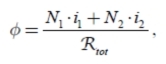
where the total reluctance is calculated as follows:

The magnetic flux in the core is:

2.3 Flux Linkage
In magnetic circuits with windings, such as Fig. 1.1, when the magnetic field in the core varies with time, an induced voltage e is produced at the terminals, which is calculated by Faraday’s law:

.....................(1.15)
where N is the number of turns, φ is the time-varying magnetic flux, and λ is the flux linkage of the winding (coil) in weber-turns (Wb · t).
For a magnetic circuit with a linear relationship between B and H, λ-i relationship is defined by :

..............(1.16)
where L is the inductance in Henry (H).
2.4 Magnetic Materials
In the context of transformer manufacturing, the importance of magnetic materials is twofold. First, through their use it is possible to obtain large magnetic flux densities with relatively low levels of magnetizing force, which plays an important role in the performance of a transformer. Second, since magnetic materials can beused to constrain and direct magnetic fields in well-defined paths, in transformers the magnetic materials are used to maximize the coupling between the windings as well as to lower the excitation current required for transformer operation.
The relationship between B and H for a magnetic material is both nonlinear and multivalued. In general, the characteristics of the material cannot be described analytically. They are commonly presented in graphical form as a set of empirically determined curves based upon test samples of the material. The most common
curve used to describe a magnetic material is the B-H curve curve or hysteresis loop. For many engineering applications it is sufficient to describe the material using the dc or normal magnetization curve, which is a curve drawn through the maximum values of B and H at the tips of the hysteresis loops (Fitzgerald et al. 1990).
 |
| Fig. 4 B-H curve |
Related articles :
Sponsored links :
I am learning about audio transformer construction.
ReplyDelete-What is the theory behind multifilar windings?
-In a tri-filar winding, will it be better to twist three wires around each other or braid (plait)the three wires before winding them onto the transformer's magnetic core ?