
Instrument Transformer and Power Management (P1) Course
Chapter (6) : Current Transformers
6.10 Current Transformer Connection Groups
6.10.1 Introduction
The current circuits of relay protection systems and the indicating metering instruments are connected to the secondary windings of the current transformers.
Depending upon the circuits and protection they must serve, the current transformers will have their secondaries connected in different ways, the most common of which are those shown in Fig. (1).
The star connection shown in Fig. (1) will provide response to all forms of single -phase and interphase short circuits. An II incomplete II ( V) star connection ( shown in Fig. 1 (b )) will only be able to provide response to all kinds of interphase short circuits.
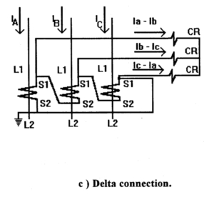
A delta connection ( Fig. 1 ( c ) ) will also respond to all kindes of interphase short circuits. With the aid of this connection the difference of the phase currents can be obtained and used to advantage for relay protection purposes.
In the circuit of Fig. l(d) the secondaries are connected for the difference of the currents of the two phases. This connection will respond to all kinds of interphase short circuits.
Connection of the secondaries for the sum of all three phases currents (Fig. l(e )) can only provide response to single -phase short circuits to earth.
It is known that the vector sum of the load currents in each phase, as will as of the fault currents which flow when a three phase or phase -to -phase short circuit occurs, will be zero. Therefore, practically no current will be able to flow through the current relay in the circuit of Fig. 1 ( e) during such conditions ( a certain small unbalance current will flow because of slight differences in the characteristics of the current transformers) .
If, however, a single -phase short circuit occurs, the vector sum of the currents will not be zero because the fault current only flows through the shorted phase. This results in a flow of secondary current which energizes the protective current relay (CRO)
Instead of the circuit of Fig. l(e) ; the current relay CRO is frequently interposed in the neutral conductor between star connected current transformers and star - connected relay coils as shown in Fig. 1 ( a). The relay will respond in the same way as in the connection of Fig. l(e ).
The basic over current relay connections using related group of current transformers connections are shown in Table (1) .


a) Transformer with single core and secondary winding.
b ) Transformer with two cores and secondary windings.


6.10.2 Types of current transformer connections :
1 ) C.T's connection in parallel.
2 ) C.T's connection in star.
3) C.T's connection in delta.
6.10.2.1 The connection in parallel

In this method the total current output which go through the ammeter or the relay at the normal case must be equal zero, so the relay must be not operate because, I1 + I2 + I3 = 0 , at any fault occur on any phase the result of reminder currents not equal zero.
Assume I1 = 0 then I2 + I3 not equal zero and the relay operate at I1 = 0 , I2 = 0 then 1J pass through the relay and the relay operate by the same current because I total = 13°.

6.10.2.2 The connection in star
This method is more similar to that of the parallel case with some additional relay in the neutral lead for the earth fault current as indicator to it.
6.10.2.3 The connection in delta

There are two methods in the delta connection, the correct delta and the reverse delta. In the correct delta as shown Ir , Is ,It are the three secondary currents of the three phase current transformer, the primary currents are: Ir , Is and It.
The resultant three currents through relay coils are: Il , I2 and I3

It is clear that
It is clear also that :
In the reverse delta connection as shown in the following fig. Ir , Is , It are the three secondary currents of the three phase current transformer, the primary currents are Ir , Is and It.

Sponsored Articles :